Bond / link aggregation
A bonding interface aggregates multiple network interfaces into a single logical interface (referred to as a bond, LAG, EtherChannel, or port-channel).
The behavior of a bonding interface depends on the selected mode. Modes provide either fault tolerance or a combination of load balancing and fault tolerance. Additionally, the bonding interface can be configured for link integrity monitoring.
Configuration
Common interface configuration
Configure the interface with one or more IP addresses.
The following options are available:
address: Assign one or more IPv4 or IPv6 addresses to the interface. For example, use 192.0.2.1/24 for IPv4 or 2001:db8::1/64 for IPv6.
dhcp: The interface obtains an IPv4 address from a DHCP server on the same network segment.
dhcpv6: The interface obtains an IPv6 address from a DHCPv6 server on the same network segment.
Note
If the interface obtains an IPv4 address via DHCP, and specific adjustments are needed before/after the IP address is obtained, use the provided hook scripts:
/config/scripts/dhcp-client/pre-hooks.d//config/scripts/dhcp-client/post-hooks.d/
Example:
set interfaces bonding bond0 address 192.0.2.1/24
set interfaces bonding bond0 address 2001:db8::1/64
set interfaces bonding bond0 address dhcp
set interfaces bonding bond0 address dhcpv6
Configure a clear, descriptive alias for the interface.
This alias appears in the show interfaces command and SNMP-based
monitoring tools.
Example:
set interfaces bonding bond0 description 'This is an interface running on VyOS.'
Disable the interface.
The interface will be set to the administratively down
(A/D) state.
Example:
set interfaces bonding bond0 disable
Disable Ethernet flow control (IEEE 802.3x pause frames) on the interface.
Ethernet flow control, defined by the IEEE 802.3x standard, temporarily stops data transmission to prevent packet loss during network congestion. For example, when a sender transmits data faster than the receiver can process it.
Disabling Ethernet flow control means the interface will not signal the connected device to pause transmission and will drop packets if overwhelmed.
Example:
set interfaces bonding bond0 disable-flow-control
Disable physical link-state change detection on the interface, such as when a cable is unplugged.
By default, the interface detects physical link-state changes.
Example:
set interfaces bonding bond0 disable-link-detect
Configure a custom MAC address on the interface.
Example:
set interfaces bonding bond0 mac '00:53:01:02:03:04'
Configure the MTU on the interface.
This value defines the largest packet size, in bytes, that the interface transmits without fragmentation.
Example:
set interfaces bonding bond0 mtu 1600
Configure the MSS advertised in outgoing TCP SYN packets on the specified interface.
By clamping the MSS value in TCP SYN packets, you explicitly inform the remote side not to send packets larger than that size. This prevents connection issues that occur when Path MTU Discovery (PMTUD) fails.
The following options are available:
mss: Sets the MSS to a specific value, in bytes. Use this option if you need to enforce a specific MSS, for example, to troubleshoot connectivity issues or accommodate specific network requirements.
clamp-mss-to-pmtu: The router automatically calculates the MSS to be the interface’s MTU minus 40 bytes for IPv4 traffic (20 bytes for the IPv4 header and 20 bytes for the TCP header). This option is recommended to automatically set the proper value.
Configure how long an ARP entry remains valid after learning an IP-to-MAC address mapping on this interface.
The default duration is 30 seconds.
An ARP entry remains valid if it receives positive feedback from higher-level protocols.
Example:
set interfaces bonding bond0 ip arp-cache-timeout 180
Configure ARP filtering on this interface.
Default behavior: The kernel responds to ARP requests on this interface only if the traffic would be routed back to the ARP sender through that specific interface.
If configured: The kernel responds to ARP requests on this interface for any IP address configured on the local host, regardless of which specific interface that IP address is assigned to, and regardless of the routing table. This reflects the Linux concept that IP addresses belong to the host, not individual interfaces.
Example:
set interfaces bonding bond0 ip disable-arp-filter
Configure the interface for host or router behavior.
If configured, the interface switches to host mode, and IPv4 forwarding is disabled on it.
Example:
set interfaces bonding bond0 ip disable-forwarding
Configure whether to forward IP-directed broadcast packets received on this interface.
Default behavior: IP-directed broadcast packets are dropped.
If configured: IP-directed broadcast packets are forwarded to all hosts on the destination subnet, as defined in RFC 1812 and RFC 2644.
Example:
set interfaces bonding bond0 ip enable-directed-broadcast
Configure how to process gratuitous ARPs on this interface.
If configured, an IP-to-MAC address mapping is added to the ARP table based on gratuitous ARP requests or replies.
Note
If the ARP table already contains the IP address from a gratuitous ARP, its entry is updated regardless of whether this setting is configured.
Example:
set interfaces bonding bond0 ip enable-arp-accept
Configure the source IP selection for ARP requests on this interface.
Default behavior: The kernel can use any IP address the host owns as the source IP address in ARP requests on this interface.
If configured: The kernel first attempts to select a source IP address configured on the interface that shares a common subnet with the target IP address. If there is no such subnet, the kernel selects the IP address it would normally use (based on the routing table to reach the target destination).
Example:
set interfaces bonding bond0 ip enable-arp-announce
Configure which ARP requests will be ignored on this interface.
Default behavior: The kernel responds to ARP requests for any local IP addresses, regardless of which interface they are assigned to.
If configured: The kernel responds to ARP requests only if the target IP address is assigned to this specific interface.
Example:
set interfaces bonding bond0 ip enable-arp-ignore
Configure proxy ARP on this interface.
If configured, the router (kernel) intercepts ARP requests for non-local IP addresses and replies with the MAC address of the interface that received the request. Subsequent packets destined to these IP addresses are forwarded to their actual destinations on remote subnets.
Example:
set interfaces bonding bond0 ip enable-proxy-arp
Configure local proxy ARP on the interface.
If configured, the router (kernel) responds to ARP requests on this VLAN interface even if the target IP address resides on the same subnet and interface.
This is used to support network isolation requirements (RFC 3069) for private VLANs (PVLANs). In PVLAN configurations, hosts on isolated ports are NOT allowed to communicate directly with each other at Layer 2, but they can communicate with the upstream router.
By replying to inter-host ARP requests with its own MAC address, the router (kernel) directs inter-host traffic through itself instead of directly between hosts.
Note
This command works independently and does not require enabling the standard proxy ARP on the interface.
Local proxy ARP is also known as:
VLAN aggregation (RFC 3069).
Private VLAN (Cisco, Allied Telesyn).
Source-port filtering or port isolation (Hewlett-Packard).
MAC-Forced Forwarding (Ericsson).
Configure source IP address validation using RPF on this interface, as specified in RFC 3704.
The following options are available:
strict: Each incoming packet’s source IP address is checked against the Forwarding Information Base (FIB). If the interface is not the best route back to that source, validation fails, and the packet is dropped.
loose: Each incoming packet’s source IP address is checked against the FIB. If the source IP address is unreachable through any interface, validation fails.
disable: No source IP address validation is performed. All incoming packets are accepted.
RFC 3704 recommends enabling strict mode to prevent IP spoofing, such as DDoS attacks. For asymmetric or other complex routing scenarios, use loose mode.
Configure the interface to automatically obtain an IPv6 address using SLAAC, as specified in RFC 4862.
IPv6 hosts can configure themselves automatically when connected to an IPv6 network using the Neighbor Discovery Protocol via ICMPv6 router discovery messages. When first connected to a network, a host sends a link-local router solicitation multicast request for its configuration parameters. The router responds with a router advertisement packet containing Internet Layer configuration parameters.
Note
This method automatically disables IPv6 traffic forwarding on the interface.
Example:
set interfaces bonding bond0 ipv6 address autoconf
Configure the interface to assign itself an IPv6 address using the EUI-64 method, as specified in RFC 4291.
Example:
set interfaces bonding bond0 ipv6 address eui64 2001:db8:beef::/64
Disable the automatic assignment of a link-local IPv6 address to this interface.
Example:
set interfaces bonding bond0 ipv6 address no-default-link-local
Configure the interface for host or router behavior.
If configured, the interface switches to host mode, and IPv6 forwarding is disabled on it.
Example:
set interfaces bonding bond0 ipv6 disable-forwarding
Configure the MSS advertised in outgoing TCP SYN packets on the specified interface.
By clamping the MSS value in TCP SYN packets, you explicitly inform the remote side not to send packets larger than that size. This prevents connection issues when Path MTU Discovery (PMTUD) fails.
The following options are available:
mss: Set the MSS to a specific value, in bytes. Use this option to enforce a specific MSS, for example, to troubleshoot connectivity issues or accommodate specific network requirements.
clamp-mss-to-pmtu: The router calculates the MSS to be the interface’s MTU minus 60 bytes for IPv6 traffic (40 bytes for the IPv6 header and 20 bytes for the TCP header). This option is recommended to automatically set the proper value.
Configure IPv6 DAD on the interface.
The following options are available:
0: Disables DAD. No duplicate address detection is performed.
1: Enables DAD (default). Duplicate addresses are detected. The interface’s IPv6 operation continues for valid IPv6 addresses.
2: Enables DAD and, if a MAC-based duplicate link-local address is found, disables IPv6 operation on this interface.
Example:
set interfaces bonding bond0 ipv6 accept-dad 2
Configure the number of DAD messages that the router (kernel) sends during IPv6 address assignment on this interface.
The default value is 1.
Example:
set interfaces bonding bond0 ipv6 dup-addr-detect-transmits 5
Assign the interface to a specific VRF instance.
See also
For information on configuring a VRF, refer to the VRF section.
Example:
set interfaces bonding bond0 vrf red
DHCP(v6)
Configure a DHCP client identifier for the interface, as specified in RFC 2131.
The client-id is an identifier that the DHCP client sends to the DHCP
server to uniquely identify itself for IP address assignment. By default,
the client uses its MAC address. The <description> is a user-defined
string that will be sent to the DHCP server as the DHCP client identifier.
Example:
set interfaces bonding bond0 dhcp-options client-id 'foo-bar'
Configure a specific hostname for the interface.
Instead of the real hostname, the DHCP client will send the specific hostname to the DHCP server when requesting an IP address.
Example:
set interfaces bonding bond0 dhcp-options host-name 'VyOS'
Configure the DHCP client to include a vendor-class identifier in its DHCP requests on this interface.
The vendor-class identifier is a vendor-specific byte string that enables the DHCP server to identify the device and, in some cases, provide configuration options.
Example:
set interfaces bonding bond0 dhcp-options vendor-class-id 'VyOS'
Configure the DHCP client to obtain an IP address, but ignore any default gateway provided by the DHCP server on this interface.
Example:
set interfaces bonding bond0 dhcp-options no-default-route
Configure the distance for the default route obtained from the DHCP server on this interface.
Example:
set interfaces bonding bond0 dhcp-options default-route-distance 220
Configure the DHCP client to reject the specific IP address or IP address range from the DHCP server on this interface.
This is useful when a modem assigns a local IP address upon start. To reject multiple addresses, run this command multiple times with different values. You can reject individual addresses (192.168.100.1) or entire subnets (192.168.100.0/24).
Example:
set interfaces bonding bond0 dhcp-options reject 192.168.100.0/24
Configure the DHCP client to send a specific user-class identifier in its DHCP requests on this interface.
The DHCP server can interpret this identifier and provide specific configuration options based on it (for example, default routes). The user-class value typically groups DHCP clients with similar configuration needs (for example, employees, guests, or printers).
Example:
set interfaces bonding bond0 dhcp-options user-class VyOS
Configure a specific DUID for the DHCPv6 client on this interface.
The DUID is an identifier used by a DHCPv6 client to get an IPv6 address from a DHCPv6 server. It consists of a 2-byte type field, followed by a variable-length identifier field up to 128 bytes. The format of the identifier part depends on the DUID type:
DUID-LLT: The most common type, which includes a hardware type, a timestamp, and a MAC address.
DUID-EN: Is based on a vendor’s enterprise number and a unique identifier assigned by the vendor.
DUID-LL: Includes only a MAC address.
The DHCP server matches the DUID against its database and provides configuration data (such as address, lease times, DNS servers, etc.) to the DHCP client.
Example:
set interfaces bonding bond0 duid '0e:00:00:01:00:01:27:71:db:f0:00:50:56:bf:c5:6d'
Configure the DHCP client not to send a release message when it stops running on this interface.
This helps retain the assigned address or prefix.
Example:
set interfaces bonding bond0 dhcpv6-options no-release
Enable a stateless DHCPv6 client mode on this interface.
In stateless mode, the DHCPv6 client requests only stateless configuration parameters from the DHCP server (for example, DNS server addresses). It doesn’t request a stateful configuration, such as IPv6 addresses or prefixes.
Example:
set interfaces bonding bond0 dhcpv6-options parameters-only
Enable DHCPv6 rapid commit on this interface.
When enabled, the DHCP client and server skip the negotiation steps (Advertise and Request), completing the DHCPv6 configuration process in just two messages (Solicit and final Reply).
Example:
set interfaces bonding bond0 dhcpv6-options rapid-commit
Configure the DHCPv6 client to request a temporary IPv6 address on this interface.
When configured, the DHCP client doesn’t form an Identity Association for Non-temporary Addresses (IA_NA) partnership. Consequently, it only obtains a temporary IPv6 address and doesn’t obtain a permanent one.
Example:
set interfaces bonding bond0 dhcpv6-options temporary
DHCPv6 Prefix Delegation (PD)
VyOS supports DHCPv6 Prefix Delegation (DHCPv6-PD) as described in RFC 3633. DHCPv6-PD is supported by most ISPs that provide native IPv6 for consumers on fixed networks.
Configure a specific prefix length for DHCPv6-PD requests on this interface.
Some ISPs provide only a /64 prefix by default. Use this command to request a different prefix length for a specific DHCPv6-PD request, ranging from /32 (if allowed by your ISP) down to /64. <id> is a unique identifier for the DHCPv6-PD request.
The default value is 64.
To request a /56 prefix from your ISP, use:
set interfaces bonding bond0 dhcpv6-options pd 0 length 56
Configure the IPv6 interface identifier (host portion) for the delegatee interface.
The value must be a decimal integer. It is appended to the delegated prefix and the configured SLA ID to form the final IPv6 address.
By default, the host portion is generated based on the parent interface’s MAC address (EUI-64 format).
Example:
If a /64 prefix is delegated to interface eth8 and you configure the host portion as 65535, the resulting IPv6 address will end with ::ffff, as 65535 corresponds to ffff in hexadecimal notation.
set interfaces bonding bond0 dhcpv6-options pd 0 interface eth8 address 65534
Configure the SLA ID for the delegatee interface.
The value must be a decimal integer greater than 0 and fit in the length of SLA IDs. It is converted to hexadecimal and appended to the delegated prefix to form the specific subnet prefix for the delegatee interface.
Example:
If SLA ID is 1 and the delegated prefix is 2001:db8:ffff::/48, the
resulting subnet prefix for the delegatee interface will be
2001:db8:ffff:1::/64.
set interfaces bonding bond0 dhcpv6-options pd 0 interface eth8 sla-id 1
Member interfaces
Add an interface to the bonding group.
Example:
To configure eth0 and eth1 as members of the bonding interface bond0, execute the following commands:
set interfaces bonding bond0 member interface eth0
set interfaces bonding bond0 member interface eth1
Bond modes
Configure the bonding mode on the interface. The default mode is
802.3ad.The available modes are:
802.3ad
Description:
IEEE 802.3ad Dynamic Link Aggregation. Groups only member interfaces with the same speed (e.g., 1 Gbps) and duplex settings. Member interfaces with different speed and duplex settings are not included in the active bond.
Provides load balancing and fault tolerance. Uses the LACP to negotiate the bond with the switch.
Traffic distribution:
Traffic is distributed according to the transmit hash policy (default: XOR).
The bonding driver applies an XOR operation to specific packet header fields, generating a hash value that maps to a particular member interface. This ensures the same network flow is consistently transmitted over the same member interface.
The transmit hash policy is configured via the
hash-policyoption.Failover:
If a member interface fails, the hash is recalculated to distribute traffic among the remaining active member interfaces.
Note
Not all transmit hash policies comply with 802.3ad, particularly section 43.2.4. Using a non-compliant policy may result in out-of-order packet delivery.
active-backup
Description:
Provides fault tolerance. Only one member interface is active at a time. Other member interfaces remain in a standby mode.
Traffic distribution:
All traffic (incoming and outgoing) is routed via one active member interface.
Failover:
If the designated member interface fails, all traffic is routed to another member interface. The bonding driver sends a Gratuitous ARP to update the peer’s MAC address table, linking the bond’s MAC address to another physical port.
broadcast
Description:
Provides maximum fault tolerance by duplicating traffic.
Traffic distribution:
Every packet is duplicated and transmitted on all member interfaces.
Failover:
Traffic flow is not interrupted as long as at least one member interface remains active.
round-robin
Description:
Provides load balancing and fault tolerance.
Traffic distribution:
Packets are transmitted in sequential order across the member interfaces (e.g., packet 1 > interface A, packet 2 > interface B, etc.).
Failover:
If a member interface fails, the sequence skips the failed interface and continues with the remaining active members.
transmit-load-balance
Description:
Provides adaptive transmit load balancing and fault tolerance.
Traffic distribution:
Outgoing: Distributed across all active member interfaces based on the current load.
Incoming: Received by a designated member interface (active receiver).
Failover:
If the active receiver fails, another member interface takes over as the new active receiver.
adaptive-load-balance
Description:
Provides adaptive transmit load balancing identical to
transmit-load-balance, receive load balancing for IPv4 traffic, and fault tolerance for both incoming and outgoing traffic.Traffic distribution:
Outgoing: Identical to
transmit-load-balance.Incoming: Distributed based on ARP manipulation. For both local and remote connections, the bonding driver intercepts ARP traffic and changes the source MAC address to the MAC address of the least loaded member interface.
All traffic from that peer is then routed to the chosen member interface.
Failover:
If a member interface’s state changes (fails, recovers, is added, or excluded), the traffic is redistributed among all active member interfaces.
xor-hash: Provides load balancing and fault tolerance based on a hash formula. Distributes traffic and handles failover identically to802.3ad, but operates without the LACP.
Configure how many member interfaces must be active (in the link-up state) to mark the bonding interface UP (carrier asserted).
This command applies only when the bonding interface is configured in 802.3ad mode and functions like the Cisco EtherChannel min-links feature. It ensures that a bonding interface is marked UP (carrier asserted) only when a specified number of member interfaces are active (in the link-up state). This helps guarantee a minimum level of bandwidth for higher-level services (such as clustering) relying on the bonding interface.
The default value is 0. This marks the bonding interface UP (carrier asserted) whenever an active LACP aggregator exists, regardless of the number of member interfaces in that aggregator.
Note
In 802.3ad mode, a bond cannot be active without at least one active member interface. Therefore, setting min-links to 0 or 1 has the same result: the bonding interface is marked UP (carrier asserted).
Configure the rate at which the bonding interface requests its link partner to send LACPDUs in 802.3ad mode.
This command applies only when the bonding interface is configured in 802.3ad mode.
The following options are available:
slow (default): Requests the link partner to transmit LACPDUs every 30 seconds.
fast: Requests the link partner to transmit LACPDUs every 1 second.
Configure a specific MAC address for the bonding interface.
This sets the 802.3ad system MAC address, which is used for LACPDU exchanges with the link partner. You can assign a fixed MAC address or generate a random one for these LACPDU exchanges.
Configure which transmit hash policy to use for distributing traffic across member interfaces.
The following policies are available:
layer2Description:
Routes all traffic destined for a specific network peer through the same member interface. The policy is 802.3ad-compliant.
Hash inputs:
Source MAC address, destination MAC address, and Ethernet packet type ID.
Formula:
hash = source MAC address XOR destination MAC address XOR packet type ID
member interface number = hash modulo member interface count
layer2+3Description:
Similar to
layer2, routes all traffic destined for a specific network peer through the same member interface and is IEEE 802.3ad-compliant. Uses both Layer 2 and Layer 3 information to provide a more balanced traffic distribution.Hash inputs:
Source MAC address, destination MAC address, and Ethernet packet type ID.
Source IP address, destination IP address. IPv6 addresses are first hashed using
IPv6_addr_hash.
Formula:
hash = source MAC address XOR destination MAC address XOR packet type ID
hash = hash XOR source IP address XOR destination IP address
hash = hash XOR (hash RSHIFT 16)
hash = hash XOR (hash RSHIFT 8)
member interface number = hash modulo member interface count
For non-IP traffic, the formula is the same as for
layer2.layer3+4Description:
Routes different connections (flows) destined for a specific network peer through multiple member interfaces, but ensures each individual flow is routed through only one member interface.
Note
This policy is not fully 802.3ad-compliant. When a single TCP or UDP flow contains both fragmented and unfragmented packets, the algorithm may distribute them across different member interfaces. This may result in out-of-order packet delivery, violating the 802.3ad standard.
Hash inputs:
Source port, destination port (if available).
Source IP address, destination IP address. IPv6 addresses are first hashed using
IPv6_addr_hash.
Formula:
hash = source port, destination port (as in the header)
hash = hash XOR source IP address XOR destination IP address
hash = hash XOR (hash RSHIFT 16)
hash = hash XOR (hash RSHIFT 8)
member interface number = hash modulo member interface count
For fragmented TCP or UDP packets and all other IPv4 and IPv6 traffic, the source and destination port information is omitted.
For non-IP traffic, the formula is the same as for
layer2.
Configure the primary member interface in the bond.
The primary member interface remains active as long as it is operational; alternative member interfaces are used only if it fails.
Use this configuration when a specific member interface is preferred, such as one with higher throughput.
This command applies only to active-backup, transmit-load-balance, and
adaptive-load-balance modes.
Configure the ARP monitoring interval, in seconds, for the bonding interface.
ARP monitoring periodically assesses the health of each member interface by checking whether it has recently sent or received traffic (this criterion varies depending on the bonding mode and the member interface’s state). ARP probes are sent to the IP addresses specified with the arp-monitor target option.
When ARP monitoring is used with EtherChannel-compatible modes (such as
round-robin or xor-hash), the switch should be configured to distribute
traffic across all member interfaces. If the switch distributes traffic using
an XOR-based policy, all ARP replies will be received on one member interface,
causing other member interfaces to be incorrectly marked as failed.
Setting this value to 0 disables ARP monitoring.
The default value is 0.
Configure the IP addresses for ARP monitoring requests.
The bonding driver sends ARP requests to these IP addresses to check the state of member interfaces.
To enable ARP monitoring, configure at least one IP address (up to 16 per bonding interface).
By default, no IP addresses are configured.
VLAN
IEEE 802.1q, often referred to as Dot1q, is the industry standard for implementing VLANs on Ethernet networks. It defines VLAN tagging for Ethernet frames and outlines procedures for bridges and switches. The standard also includes quality-of-service prioritization (IEEE 802.1p) and defines the Generic Attribute Registration Protocol.
VLAN-aware network segments (i.e., IEEE 802.1q conformant) use VLAN tags. When a frame enters such a segment, a tag is added to indicate VLAN membership. Each frame can belong to only one VLAN. If a frame arrives without a tag, it is assumed to be part of the native VLAN.
IEEE 802.1, a working group of the IEEE 802 standards committee, has developed the standard and continues to revise it. One notable revision is 802.1Q-2014, which incorporated IEEE 802.1aq (Shortest Path Bridging) and much of the IEEE 802.1d standard.
In VyOS, 802.1q VLAN interfaces are represented as virtual subinterfaces,
referred to as vif.
Configure a VLAN interface with a unique VLAN ID.
VLAN ID identifies a specific VLAN and ranges from 0 to 4094.
You can configure multiple VLAN interfaces on a single physical interface.
Note
Only 802.1Q-tagged packets are accepted on Ethernet vifs.
Configure the interface with one or more IP addresses.
The following options are available:
address: Assign one or more IPv4 or IPv6 addresses to the interface. For example, use 192.0.2.1/24 for IPv4 or 2001:db8::1/64 for IPv6.
dhcp: The interface obtains an IPv4 address from a DHCP server on the same network segment.
dhcpv6: The interface obtains an IPv6 address from a DHCPv6 server on the same network segment.
Note
If the interface obtains an IPv4 address via DHCP, and specific adjustments are needed before/after the IP address is obtained, use the provided hook scripts:
/config/scripts/dhcp-client/pre-hooks.d//config/scripts/dhcp-client/post-hooks.d/
Example:
set interfaces bonding bond0 vif 10 address 192.0.2.1/24
set interfaces bonding bond0 vif 10 address 2001:db8::1/64
set interfaces bonding bond0 vif 10 address dhcp
set interfaces bonding bond0 vif 10 address dhcpv6
Configure a clear, descriptive alias for the interface.
This alias appears in the show interfaces command and SNMP-based
monitoring tools.
Example:
set interfaces bonding bond0 vif 10 description 'This is an interface running on VyOS.'
Disable the interface.
The interface will be set to the administratively down
(A/D) state.
Example:
set interfaces bonding bond0 vif 10 disable
Disable physical link-state change detection on the interface, such as when a cable is unplugged.
By default, the interface detects physical link-state changes.
Example:
set interfaces bonding bond0 vif 10 disable-link-detect
Configure a custom MAC address on the interface.
Example:
set interfaces bonding bond0 vif 10 mac '00:53:01:02:03:04'
Configure the MTU on the interface.
This value defines the largest packet size, in bytes, that the interface transmits without fragmentation.
Example:
set interfaces bonding bond0 vif 10 mtu 1600
Configure the MSS advertised in outgoing TCP SYN packets on the specified interface.
By clamping the MSS value in TCP SYN packets, you explicitly inform the remote side not to send packets larger than that size. This prevents connection issues that occur when Path MTU Discovery (PMTUD) fails.
The following options are available:
mss: Sets the MSS to a specific value, in bytes. Use this option if you need to enforce a specific MSS, for example, to troubleshoot connectivity issues or accommodate specific network requirements.
clamp-mss-to-pmtu: The router automatically calculates the MSS to be the interface’s MTU minus 40 bytes for IPv4 traffic (20 bytes for the IPv4 header and 20 bytes for the TCP header). This option is recommended to automatically set the proper value.
Configure how long an ARP entry remains valid after learning an IP-to-MAC address mapping on this interface.
The default duration is 30 seconds.
An ARP entry remains valid if it receives positive feedback from higher-level protocols.
Example:
set interfaces bonding bond0 vif 10 ip arp-cache-timeout 180
Configure ARP filtering on this interface.
Default behavior: The kernel responds to ARP requests on this interface only if the traffic would be routed back to the ARP sender through that specific interface.
If configured: The kernel responds to ARP requests on this interface for any IP address configured on the local host, regardless of which specific interface that IP address is assigned to, and regardless of the routing table. This reflects the Linux concept that IP addresses belong to the host, not individual interfaces.
Example:
set interfaces bonding bond0 vif 10 ip disable-arp-filter
Configure the interface for host or router behavior.
If configured, the interface switches to host mode, and IPv4 forwarding is disabled on it.
Example:
set interfaces bonding bond0 vif 10 ip disable-forwarding
Configure whether to forward IP-directed broadcast packets received on this interface.
Default behavior: IP-directed broadcast packets are dropped.
If configured: IP-directed broadcast packets are forwarded to all hosts on the destination subnet, as defined in RFC 1812 and RFC 2644.
Example:
set interfaces bonding bond0 vif 10 ip enable-directed-broadcast
Configure how to process gratuitous ARPs on this interface.
If configured, an IP-to-MAC address mapping is added to the ARP table based on gratuitous ARP requests or replies.
Note
If the ARP table already contains the IP address from a gratuitous ARP, its entry is updated regardless of whether this setting is configured.
Example:
set interfaces bonding bond0 vif 10 ip enable-arp-accept
Configure the source IP selection for ARP requests on this interface.
Default behavior: The kernel can use any IP address the host owns as the source IP address in ARP requests on this interface.
If configured: The kernel first attempts to select a source IP address configured on the interface that shares a common subnet with the target IP address. If there is no such subnet, the kernel selects the IP address it would normally use (based on the routing table to reach the target destination).
Example:
set interfaces bonding bond0 vif 10 ip enable-arp-announce
Configure which ARP requests will be ignored on this interface.
Default behavior: The kernel responds to ARP requests for any local IP addresses, regardless of which interface they are assigned to.
If configured: The kernel responds to ARP requests only if the target IP address is assigned to this specific interface.
Example:
set interfaces bonding bond0 vif 10 ip enable-arp-ignore
Configure proxy ARP on this interface.
If configured, the router (kernel) intercepts ARP requests for non-local IP addresses and replies with the MAC address of the interface that received the request. Subsequent packets destined to these IP addresses are forwarded to their actual destinations on remote subnets.
Example:
set interfaces bonding bond0 vif 10 ip enable-proxy-arp
Configure local proxy ARP on the interface.
If configured, the router (kernel) responds to ARP requests on this VLAN interface even if the target IP address resides on the same subnet and interface.
This is used to support network isolation requirements (RFC 3069) for private VLANs (PVLANs). In PVLAN configurations, hosts on isolated ports are NOT allowed to communicate directly with each other at Layer 2, but they can communicate with the upstream router.
By replying to inter-host ARP requests with its own MAC address, the router (kernel) directs inter-host traffic through itself instead of directly between hosts.
Note
This command works independently and does not require enabling the standard proxy ARP on the interface.
Local proxy ARP is also known as:
VLAN aggregation (RFC 3069).
Private VLAN (Cisco, Allied Telesyn).
Source-port filtering or port isolation (Hewlett-Packard).
MAC-Forced Forwarding (Ericsson).
Configure source IP address validation using RPF on this interface, as specified in RFC 3704.
The following options are available:
strict: Each incoming packet’s source IP address is checked against the Forwarding Information Base (FIB). If the interface is not the best route back to that source, validation fails, and the packet is dropped.
loose: Each incoming packet’s source IP address is checked against the FIB. If the source IP address is unreachable through any interface, validation fails.
disable: No source IP address validation is performed. All incoming packets are accepted.
RFC 3704 recommends enabling strict mode to prevent IP spoofing, such as DDoS attacks. For asymmetric or other complex routing scenarios, use loose mode.
Configure the interface to automatically obtain an IPv6 address using SLAAC, as specified in RFC 4862.
IPv6 hosts can configure themselves automatically when connected to an IPv6 network using the Neighbor Discovery Protocol via ICMPv6 router discovery messages. When first connected to a network, a host sends a link-local router solicitation multicast request for its configuration parameters. The router responds with a router advertisement packet containing Internet Layer configuration parameters.
Note
This method automatically disables IPv6 traffic forwarding on the interface.
Example:
set interfaces bonding bond0 vif 10 ipv6 address autoconf
Configure the interface to assign itself an IPv6 address using the EUI-64 method, as specified in RFC 4291.
Example:
set interfaces bonding bond0 vif 10 ipv6 address eui64 2001:db8:beef::/64
Disable the automatic assignment of a link-local IPv6 address to this interface.
Example:
set interfaces bonding bond0 vif 10 ipv6 address no-default-link-local
Configure the interface for host or router behavior.
If configured, the interface switches to host mode, and IPv6 forwarding is disabled on it.
Example:
set interfaces bonding bond0 vif 10 ipv6 disable-forwarding
Configure the MSS advertised in outgoing TCP SYN packets on the specified interface.
By clamping the MSS value in TCP SYN packets, you explicitly inform the remote side not to send packets larger than that size. This prevents connection issues when Path MTU Discovery (PMTUD) fails.
The following options are available:
mss: Set the MSS to a specific value, in bytes. Use this option to enforce a specific MSS, for example, to troubleshoot connectivity issues or accommodate specific network requirements.
clamp-mss-to-pmtu: The router calculates the MSS to be the interface’s MTU minus 60 bytes for IPv6 traffic (40 bytes for the IPv6 header and 20 bytes for the TCP header). This option is recommended to automatically set the proper value.
Configure IPv6 DAD on the interface.
The following options are available:
0: Disables DAD. No duplicate address detection is performed.
1: Enables DAD (default). Duplicate addresses are detected. The interface’s IPv6 operation continues for valid IPv6 addresses.
2: Enables DAD and, if a MAC-based duplicate link-local address is found, disables IPv6 operation on this interface.
Example:
set interfaces bonding bond0 vif 10 ipv6 accept-dad 2
Configure the number of DAD messages that the router (kernel) sends during IPv6 address assignment on this interface.
The default value is 1.
Example:
set interfaces bonding bond0 vif 10 ipv6 dup-addr-detect-transmits 5
Assign the interface to a specific VRF instance.
See also
For information on configuring a VRF, refer to the VRF section.
Example:
set interfaces bonding bond0 vif 10 vrf red
DHCP(v6)
Configure a DHCP client identifier for the interface, as specified in RFC 2131.
The client-id is an identifier that the DHCP client sends to the DHCP
server to uniquely identify itself for IP address assignment. By default,
the client uses its MAC address. The <description> is a user-defined
string that will be sent to the DHCP server as the DHCP client identifier.
Example:
set interfaces bonding bond0 vif 10 dhcp-options client-id 'foo-bar'
Configure a specific hostname for the interface.
Instead of the real hostname, the DHCP client will send the specific hostname to the DHCP server when requesting an IP address.
Example:
set interfaces bonding bond0 vif 10 dhcp-options host-name 'VyOS'
Configure the DHCP client to include a vendor-class identifier in its DHCP requests on this interface.
The vendor-class identifier is a vendor-specific byte string that enables the DHCP server to identify the device and, in some cases, provide configuration options.
Example:
set interfaces bonding bond0 vif 10 dhcp-options vendor-class-id 'VyOS'
Configure the DHCP client to obtain an IP address, but ignore any default gateway provided by the DHCP server on this interface.
Example:
set interfaces bonding bond0 vif 10 dhcp-options no-default-route
Configure the distance for the default route obtained from the DHCP server on this interface.
Example:
set interfaces bonding bond0 vif 10 dhcp-options default-route-distance 220
Configure the DHCP client to reject the specific IP address or IP address range from the DHCP server on this interface.
This is useful when a modem assigns a local IP address upon start. To reject multiple addresses, run this command multiple times with different values. You can reject individual addresses (192.168.100.1) or entire subnets (192.168.100.0/24).
Example:
set interfaces bonding bond0 vif 10 dhcp-options reject 192.168.100.0/24
Configure the DHCP client to send a specific user-class identifier in its DHCP requests on this interface.
The DHCP server can interpret this identifier and provide specific configuration options based on it (for example, default routes). The user-class value typically groups DHCP clients with similar configuration needs (for example, employees, guests, or printers).
Example:
set interfaces bonding bond0 vif 10 dhcp-options user-class VyOS
Configure a specific DUID for the DHCPv6 client on this interface.
The DUID is an identifier used by a DHCPv6 client to get an IPv6 address from a DHCPv6 server. It consists of a 2-byte type field, followed by a variable-length identifier field up to 128 bytes. The format of the identifier part depends on the DUID type:
DUID-LLT: The most common type, which includes a hardware type, a timestamp, and a MAC address.
DUID-EN: Is based on a vendor’s enterprise number and a unique identifier assigned by the vendor.
DUID-LL: Includes only a MAC address.
The DHCP server matches the DUID against its database and provides configuration data (such as address, lease times, DNS servers, etc.) to the DHCP client.
Example:
set interfaces bonding bond0 vif 10 duid '0e:00:00:01:00:01:27:71:db:f0:00:50:56:bf:c5:6d'
Configure the DHCP client not to send a release message when it stops running on this interface.
This helps retain the assigned address or prefix.
Example:
set interfaces bonding bond0 vif 10 dhcpv6-options no-release
Enable a stateless DHCPv6 client mode on this interface.
In stateless mode, the DHCPv6 client requests only stateless configuration parameters from the DHCP server (for example, DNS server addresses). It doesn’t request a stateful configuration, such as IPv6 addresses or prefixes.
Example:
set interfaces bonding bond0 vif 10 dhcpv6-options parameters-only
Enable DHCPv6 rapid commit on this interface.
When enabled, the DHCP client and server skip the negotiation steps (Advertise and Request), completing the DHCPv6 configuration process in just two messages (Solicit and final Reply).
Example:
set interfaces bonding bond0 vif 10 dhcpv6-options rapid-commit
Configure the DHCPv6 client to request a temporary IPv6 address on this interface.
When configured, the DHCP client doesn’t form an Identity Association for Non-temporary Addresses (IA_NA) partnership. Consequently, it only obtains a temporary IPv6 address and doesn’t obtain a permanent one.
Example:
set interfaces bonding bond0 vif 10 dhcpv6-options temporary
DHCPv6 Prefix Delegation (PD)
VyOS supports DHCPv6 Prefix Delegation (DHCPv6-PD) as described in RFC 3633. DHCPv6-PD is supported by most ISPs that provide native IPv6 for consumers on fixed networks.
Configure a specific prefix length for DHCPv6-PD requests on this interface.
Some ISPs provide only a /64 prefix by default. Use this command to request a different prefix length for a specific DHCPv6-PD request, ranging from /32 (if allowed by your ISP) down to /64. <id> is a unique identifier for the DHCPv6-PD request.
The default value is 64.
To request a /56 prefix from your ISP, use:
set interfaces bonding bond0 vif 10 dhcpv6-options pd 0 length 56
Configure the IPv6 interface identifier (host portion) for the delegatee interface.
The value must be a decimal integer. It is appended to the delegated prefix and the configured SLA ID to form the final IPv6 address.
By default, the host portion is generated based on the parent interface’s MAC address (EUI-64 format).
Example:
If a /64 prefix is delegated to interface eth8 and you configure the host portion as 65535, the resulting IPv6 address will end with ::ffff, as 65535 corresponds to ffff in hexadecimal notation.
set interfaces bonding bond0 vif 10 dhcpv6-options pd 0 interface eth8 address 65534
Configure the SLA ID for the delegatee interface.
The value must be a decimal integer greater than 0 and fit in the length of SLA IDs. It is converted to hexadecimal and appended to the delegated prefix to form the specific subnet prefix for the delegatee interface.
Example:
If SLA ID is 1 and the delegated prefix is 2001:db8:ffff::/48, the
resulting subnet prefix for the delegatee interface will be
2001:db8:ffff:1::/64.
set interfaces bonding bond0 vif 10 dhcpv6-options pd 0 interface eth8 sla-id 1
SPAN port mirroring
SPAN port mirroring copies inbound and outbound traffic from one interface to another specified interface.
The destination interface is usually connected to specialized equipment, such as a behavior control system, an intrusion detection system, or a traffic collector, and copies all related traffic from this port. The benefit of mirroring traffic is that the application is isolated from the source traffic, so application processing does not affect the traffic or system performance.
To configure SPAN port mirroring, VyOS uses
the mirror parameter. You can mirror ingress traffic (traffic entering the
router) and egress traffic (traffic leaving the router) separately. Both
directions can be mirrored to the same destination interface or split to
different ones.
Mirror ingress traffic from a bonding interface to the specified monitoring interface.
Example: Mirror the ingress traffic from bond1 to eth3.
set interfaces bonding bond1 mirror ingress eth3
Mirror egress traffic from a bonding interface to the specified monitoring interface.
Example: Mirror the egress traffic from bond1 to eth3.
set interfaces bonding bond1 mirror egress eth3
EVPN multihoming
EVPN multihoming (EVPN-MH) is a standards-based solution (RFC 7432, RFC 8365) that enables Customer Edge (CE) devices, such as servers, to connect to two or more Provider Edge (PE) devices for redundancy and load balancing.
EVPN-MH is often used as a modern, standards-based alternative to MLAG and VTEPs.
Ethernet Segment (ES) and Ethernet Segment Identifier (ESI)
Physical links that connect a CE device to PE devices are bundled using link aggregation. This logical bundle is called an Ethernet Segment (ES) and is uniquely identified by an Ethernet Segment Identifier (ESI) within the EVPN domain.
To enable EVPN-MH, configure the same ESI on the bonding interfaces of all PE devices connected to a single CE device.
An ESI is configured by specifying either a system MAC address and a local discriminator, or an Ethernet Segment Identifier Name (ESINAME).
The following two commands generate a 10-byte Type-3 ESI by combining the system MAC and local discriminator:
Alternatively, assign an ESINAME directly as a 10-byte Type-0 ESI using the following format: 00:AA:BB:CC:DD:EE:FF:GG:HH:II.
BGP-EVPN route usage
EVPN-MH uses BGP-EVPN route types 1 and 2 for ES discovery and MAC-IP synchronization:
Type 1 (EAD-per-ES and EAD-per-EVI) routes advertise the locally attached ESs and discover remote ESs in the network.
Type 2 (MAC-IP advertisement) routes are advertised with a destination ESI, enabling MAC-IP synchronization between ES peers.
Configure the DF preference (1-65535) for the interface. A higher value indicates a higher preference to become the DF. The DF preference is configured per-ES.
The DF election process determines which interface in a specific ES forwards BUM traffic from the EVPN overlay to the connected CE device. EVPN Type-4 (Ethernet Segment) routes are used to elect the DF, implementing the preference-based election method defined in RFC 9785.
Interfaces not elected as the DF drop any BUM traffic from the EVPN overlay using non-DF filters. Similarly, traffic received from ES peers via the EVPN overlay is blocked from forwarding to the CE device to maintain split-horizon filtering with local bias.
Configure this interface as an EVPN-MH uplink interface.
If all uplink interfaces on a PE device go down, this PE device loses access to the VXLAN overlay. To prevent traffic blackholing, the PE device forces a protocol shutdown (protodown) of its downstream EVPN-MH interfaces.
The following example configures bond0 as an EVPN-MH uplink interface:
set interfaces bonding bond0 evpn uplink
Example
The following configuration example applies to all listed third-party vendors. It creates a bonding interface with two member interfaces, defines VLANs 10 and 100 on the bonding interface, and assigns an IPv4 address to each VLAN subinterface.
# Create the bonding interface bond0 with 802.3ad LACP
set interfaces bonding bond0 hash-policy 'layer2'
set interfaces bonding bond0 mode '802.3ad'

# Add the required VLANs and IPv4 addresses on them
set interfaces bonding bond0 vif 10 address 192.168.0.1/24
set interfaces bonding bond0 vif 100 address 10.10.10.1/24

# Add the member interfaces to the bonding interface
set interfaces bonding bond0 member interface eth1
set interfaces bonding bond0 member interface eth2
Note
If you are running this configuration in a virtual environment like
EVE-NG, ensure the e1000 driver is chosen for your VyOS NIC. The default
drivers, such as virtio-net-pci or vmxnet3, are incompatible with
this configuration. Specifically, ICMP messages will not be processed correctly.
To check your NIC driver, use the following command: show interfaces ethernet
eth0 physical | grep -i driver
Cisco Catalyst configuration
Configure a Cisco Catalyst switch to integrate with a two-member VyOS bonding interface.
Assign member interfaces to PortChannel:
interface GigabitEthernet1/0/23
 description VyOS eth1
 channel-group 1 mode active
!
interface GigabitEthernet1/0/24
 description VyOS eth2
 channel-group 1 mode active
!
A new interface, Port-channel1, becomes available; all configuration,
such as allowed VLAN interfaces and STP, is applied here.
interface Port-channel1
 description LACP Channel for VyOS
 switchport trunk encapsulation dot1q
 switchport trunk allowed vlan 10,100
 switchport mode trunk
 spanning-tree portfast trunk
!
Juniper EX Switch configuration
Configure a Juniper EX Series switch to integrate with a two-member VyOS bonding interface.
# Create aggregated ethernet device with 802.3ad LACP and port speeds of 10gbit/s
set interfaces ae0 aggregated-ether-options link-speed 10g
set interfaces ae0 aggregated-ether-options lacp active

# Create layer 2 on the aggregated ethernet device with trunking for our VLANs
set interfaces ae0 unit 0 family ethernet-switching port-mode trunk

# Add the required vlans to the device
set interfaces ae0 unit 0 family ethernet-switching vlan members 10
set interfaces ae0 unit 0 family ethernet-switching vlan members 100

# Add the two interfaces to the aggregated ethernet device, in this setup both
# ports are on the same switch (switch 0, module 1, port 0 and 1)
set interfaces xe-0/1/0 ether-options 802.3ad ae0
set interfaces xe-0/1/1 ether-options 802.3ad ae0

# But this can also be done with multiple switches in a stack, a virtual
# chassis on Juniper (switch 0 and switch 1, module 1, port 0 on both switches)
set interfaces xe-0/1/0 ether-options 802.3ad ae0
set interfaces xe-1/1/0 ether-options 802.3ad ae0
Aruba/HP configuration
Configure an Aruba/HP 2510G switch to integrate with a two-member VyOS bonding interface.
# Create trunk with 2 member interfaces (interface 1 and 2) and LACP
trunk 1-2 Trk1 LACP

# Add the required VLANs to the trunk
vlan 10 tagged Trk1
vlan 100 tagged Trk1
Arista EOS configuration
When deploying VyOS in environments with Arista switches, use the following blueprint as an initial setup to configure an operational LACP port-channel between the two devices.
Let’s assume the following topology:
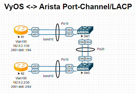
R1
interfaces {
    bonding bond10 {
        hash-policy layer3+4
        member {
            interface eth1
            interface eth2
        }
        mode 802.3ad
        vif 100 {
            address 192.0.2.1/30
            address 2001:db8::1/64
        }
    }
R2
interfaces {
    bonding bond10 {
        hash-policy layer3+4
        member {
            interface eth1
            interface eth2
        }
        mode 802.3ad
        vif 100 {
            address 192.0.2.2/30
            address 2001:db8::2/64
        }
    }
SW1
!
vlan 100
   name FOO
!
interface Port-Channel10
   switchport trunk allowed vlan 100
   switchport mode trunk
   spanning-tree portfast
!
interface Port-Channel20
   switchport mode trunk
   no spanning-tree portfast auto
   spanning-tree portfast network
!
interface Ethernet1
   channel-group 10 mode active
!
interface Ethernet2
   channel-group 10 mode active
!
interface Ethernet3
   channel-group 20 mode active
!
interface Ethernet4
   channel-group 20 mode active
!
SW2
!
vlan 100
   name FOO
!
interface Port-Channel10
   switchport trunk allowed vlan 100
   switchport mode trunk
   spanning-tree portfast
!
interface Port-Channel20
   switchport mode trunk
   no spanning-tree portfast auto
   spanning-tree portfast network
!
interface Ethernet1
   channel-group 10 mode active
!
interface Ethernet2
   channel-group 10 mode active
!
interface Ethernet3
   channel-group 20 mode active
!
interface Ethernet4
   channel-group 20 mode active
!
Note
When testing this environment in EVE-NG, ensure the e1000 driver is chosen for your VyOS network interfaces. If the default virtio driver is used, VyOS will not transmit LACP PDUs, preventing the port-channel from ever becoming active.
Operation
Show brief interface information.
vyos@vyos:~$ show interfaces bonding
Codes: S - State, L - Link, u - Up, D - Down, A - Admin Down
Interface        IP Address                        S/L  Description
---------        ----------                        ---  -----------
bond0            -                                 u/u  my-sw1 int 23 and 24
bond0.10         192.168.0.1/24                    u/u  office-net
bond0.100        10.10.10.1/24                     u/u  management-net
Show detailed interface information.
vyos@vyos:~$ show interfaces bonding bond5
bond5: <NO-CARRIER,BROADCAST,MULTICAST,MASTER,UP> mtu 1500 qdisc noqueue state DOWN group default qlen 1000
    link/ether 00:50:56:bf:ef:aa brd ff:ff:ff:ff:ff:ff
    inet6 fe80::e862:26ff:fe72:2dac/64 scope link tentative
       valid_lft forever preferred_lft forever

    RX:  bytes  packets  errors  dropped  overrun       mcast
             0        0       0        0        0           0
    TX:  bytes  packets  errors  dropped  carrier  collisions
             0        0       0        0        0           0
Show detailed information about the underlying physical links on the given bonding interface.
vyos@vyos:~$ show interfaces bonding bond5 detail
Ethernet Channel Bonding Driver: v3.7.1 (April 27, 2011)

Bonding Mode: IEEE 802.3ad Dynamic link aggregation
Transmit Hash Policy: layer2 (0)
MII Status: down
MII Polling Interval (ms): 100
Up Delay (ms): 0
Down Delay (ms): 0

802.3ad info
LACP rate: slow
Min links: 0
Aggregator selection policy (ad_select): stable

Slave Interface: eth1
MII Status: down
Speed: Unknown
Duplex: Unknown
Link Failure Count: 0
Permanent HW addr: 00:50:56:bf:ef:aa
Slave queue ID: 0
Aggregator ID: 1
Actor Churn State: churned
Partner Churn State: churned
Actor Churned Count: 1
Partner Churned Count: 1

Slave Interface: eth2
MII Status: down
Speed: Unknown
Duplex: Unknown
Link Failure Count: 0
Permanent HW addr: 00:50:56:bf:19:26
Slave queue ID: 0
Aggregator ID: 2
Actor Churn State: churned
Partner Churn State: churned
Actor Churned Count: 1
Partner Churned Count: 1